In this article you can find information about triggering possibilities using the SAGA amplifier and how to use them optimally.
1 Introduction
SAGA offers various features to accommodate triggers. This Whitepaper introduces what triggers are, how triggers can be used within the data stream and how to make optimal use of the trigger possibilities offered by SAGA.
The various trigger input options of SAGA are:
-
- 16-bit trigger input on the Docking Station
- 1-bit trigger input on the Data Recorder (DIGI input)
- Event Marker button on the Data Recorder
2 What is a trigger?
A trigger is a specific trace or marking of a certain occurrence in time. Triggers can mark an event in the data stream generated from another -independent- data stream. A ‘trigger’ in physiological experiments is often synonymous to a trace part of the total data stream that shows specific features of the signal. Events in the data stream can be marked on two different levels: sample-synchronous and as rough timing indication. The former is referred to as triggers, whilst the latter is referred to as markers. See Figure 1 for an example of an event.
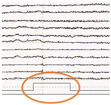
Figure 1: Signal traces including trace with marked event.
The event that is marked can be many different things, for example the presentation of a certain video or picture, the moment of a button press, or the start of a certain subroutine in a total experimental design (for example: eyes closed, eyes open in EEG experiments). The trigger provides the opportunity to analyze the measurement data in relation to the event. Obviously, the described applications have different requirements regarding the accuracy needed to mark the event.
Triggers can be used both as input to the data stream to mark different events, or as output to other devices in the case a clock pulse is generated. The focus of this article lies on how to use the triggers as input on SAGA.
3 Technical specifications: delay and jitter
As indicated in the examples mentioned above, timing can be crucial in experiments where triggers are used. There are two timing related parameters that are important to keep in mind: delay and jitter.
3.1 Introduction to delay and jitter
Within the context of triggers, the definition of delay is: the amount of time between a trigger and the signal feature it relates to; usually expressed in seconds or samples. Both signal data and triggers take time to reach their destination; while for electrical connection that time is usually neglectable; in wireless communication it may become noticeable. In addition, a trigger from an event marker button is delayed due to reaction speed of the person pressing the button. A trigger that is determined by signal processing will also be marked in time after the feature to be detected.
Jitter is defined as the variation of delay. The reaction time for pressing the button is not (exactly) the same every time. The time it takes signals to come through in wireless communication can vary due to various environmental circumstances. Jitter is an undesired side effect as it makes the delay unpredictable and therefore the timing of an event trigger less reliable.
How much delay and jitter are acceptable depends on your application and experiment design. For example, when an event trigger is used in a 2-minute recording where different stages are included, it could be that marking the exact moment one enters “stage 2” from “stage 1” is not essential for post-processing. In that case even delays up to a second, or thousands of samples could be acceptable. For event-related potentials, it is important to have a known delay - (ideally a delay of 0). When the delay is unknown or the jitter is large, you cannot determine the exact timing of the event happening. Especially in experiments that require this exact timing, delay and jitter are very important specifications.
3.2 Origin of delay and jitter
There are essentially three different mechanisms that can cause delay and jitter:
- Source reaction
The source of a trigger may need time to produce the trigger. If a trigger is merely a clock pulse, a moment in real time, then the time needed to produce that trigger can be very small. When a delay is much smaller than the sampling period of SAGA, it can be considered non-existent.
An example of a trigger source that does take time is the human reaction time. When a subject is required to press a button to mark the occurrence of an event, a delay can be observed. While the reaction time may be 0.2 s on average, it will not be exactly the same with every button press, this variation causes jitter.
- Information travel
Communicating information from a source to a destination takes time, since information cannot travel faster than the speed of light. With the relatively short distances generally used in SAGA set-ups, this limited speed causes delays which are still very small. At the speed of light, a distance of 100 m is traversed in about 0.3 µs. The time associated with a single sample at the highest sampling rate of SAGA is 244 µs.
There are other reasons for delays in information travel, which can mainly be attributed to buffering that is used as part of a communication protocol.
-
-
- In general, the information is communicated in packages and no transmission of a package occurs before it is filled, which is known as buffering. Constructing a data packet takes an amount of time which depends on the package size and the achievable data speed of the communication channel, thus introducing a delay.
For wired communication the channel data speed is much higher than for wireless communication. This means that packages of the same size can be sent more frequently, therefore causing less delay. In general, the delay of the wired communication channel is much less than a single sample time, and therefore not noticeable.
- In general, the information is communicated in packages and no transmission of a package occurs before it is filled, which is known as buffering. Constructing a data packet takes an amount of time which depends on the package size and the achievable data speed of the communication channel, thus introducing a delay.
-
-
-
- Variations in the delay may occur when the communication protocol decides to repackage the information, needs to resend a package because it got lost or when the communication channel is too busy. As a result, a package cannot be sent at the time it is ready, but needs to be delayed. Here too, the effect on wireless transmission is larger than with wired transmission due to achievable data speed. In some cases, the jitter thus caused can be larger than the (average) delay, e.g., if multiple retries are sometimes needed.
-
- Information processing
Processing information takes time. Depending on the type of processing that a filter performs on information, the information at the output of that process will be more or less delayed with respect to the input. If signal data is processed differently (e.g., low-pass filtered) from the associated trigger data (that is not further processed), then at the output a trigger event may even precede the associated signal data. In this case jitter may be caused by variations in frequency content of the signal part that makes up the event to be detected.
When triggers are generated based upon processing of the acquired signal, the processing time determines the detection of the trigger. If an event is detected by a signal exceeding a certain level, the average speed at which the signal rises may determine the time needed to reach the detection level, thus causing delay. But variations in that speed, variations in the detection level and noise on the signal will cause small variations in the detection moment which manifest themselves as jitter.
Another potential cause for delay and jitter in signal processing is when resources are limited and need to be shared. Information processing on a PC can be hindered by e.g., a virus scanner kicking in and consuming all processing power of the PC for a short period, which is known as scheduling.
4 Adding triggers to the data stream of SAGA
SAGA consists of two separable parts, the Docking Station and Data Recorder. Physiological data is measured by the Data Recorder, transferred to the Docking Station and from there transferred to the PC for storage or post-processing. Triggers can be added at various points:
- Event Marker button on the Data Recorder.
This button can be used to manually mark a certain event observed by the user or the subject. This sets a marker in the data stream. This trigger should only be used to mark events for global references in the data. Since the marker is manually set, its accuracy depends on reaction time of pressing the button. Hence this should not be used for applications that require precise timing. The button can however be used to actually measure a user’s reaction time, if combined with time accurate triggers or other synchronization signals. - DIGI input on the Data Recorder.
This input is sampled at exactly the same time as the physiological data. There is no sample mismatch between the measured physiological data and the DIGI input trigger. The DIGI input trigger is a 1-bit digital input signal, meaning that it can only mark logic High (1) or Low (0) states.
Triggers can be received by using the BNC-to-ODU7p cable. Hence, third party hardware that has a female BNC connector for sending 1-bit trigger signals can be connected to SAGA’s Data Recorder. This makes it possible to receive TTL (transistor-transistor logic) pulses from an external data acquisition device. When external hardware does not have a female BNC connector, an adapter cable is required. This adapter cable may end in a female BNC connector, or may be directly compatible to a ODU7p connector.
- Via the 16-bit trigger input on the Docking Station.
The DSUB-26 connector of the Docking Station contains 16 trigger inputs, each of which can be made logic High or Low. The data from these trigger inputs is combined to a trigger value and added to the data stream when the data from the Data Recorder has been received. If all trigger inputs are combined, this allows for over 65000 different values to be recorded, although the input is more commonly used to distinguish 16 different High/Low states. More details of the 16-bit trigger input in various use scenarios are discussed in chapter 5.
A trigger box that comes with a DSUB-26 connector can be directly connected to SAGA’s Docking Station. When the triggers are sent from a PC, the PC’s parallel port is commonly used. In this case, an adapter cable is required from the DB-25 connector (of the parallel port) to the DSUB-26 connector of SAGA’s Docking Station. Using this gives the option to use 8 trigger bits as provided by the external PC’s parallel port.
An alternative solution is to integrate SAGA with the E-Prime Chronos box and its accompanying software. The E-Prime Chronos box gives the possibility to register events such as button presses. Furthermore, 16 trigger bits are output to be registered on SAGA’s Docking Station so the trigger events are integrated in the retrieved data stream. This requires the E-Prime Chronos box, as well as the Chronos adapter for SAGA.
 Figure 2: Recommended trigger inputs available on SAGA.
5 Using the Trigger inputs
The trigger inputs can be used in various setups, with some limitations. SAGA supports stationary “desktop use” setups, mobile setups (using either the optical fiber or wireless data transmission link) and ambulatory setups. The overview in Figure 3 shows the support of the various triggers in these setups.
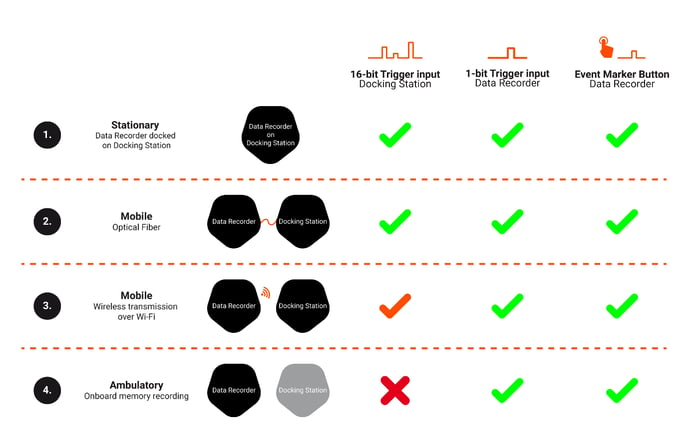 Figure 3: (Green) Setup and trigger method is supported. (Orange) Trigger method is supported but with limitations. (Red cross) trigger method not supported.
5.1 Docking Station Trigger using the stationary or optical fiber measurement setup
The triggers are sample synchronous to the physiological data whenever you are using the setup where the Data Recorder is docked onto the Docking Station or you are using the optical fiber. In these scenarios there is virtually no delay due to transport of the signal data from the Data Recorder.
This means that the Docking Station can closely match any incoming trigger with the data.
5.2 Docking Station Trigger in wireless measurement setups
When the Docking Station trigger is used in a mobile setup using the wireless data transmission link between Data Recorder and Docking Station, the triggers are added to the data stream when the data reaches the Docking Station. The wireless transmission introduces a delay between the received trigger on the Docking Station and the sampled data sent by the Data Recorder, as described in chapter 3. The sampled data may be lagging with respect to the triggers, but could also be leading with respect to the triggers. The delay can vary up to 100 ms, which is 400 samples when 4000 Hz is used as sample rate. The jitter is unpredictable. This means that the synchronicity of the triggers added to the data stream cannot be sample synchronous.
The 16-bit trigger should not be used for timing-critical experiments and event related potentials when used in a wireless setup. If you want to use the 16-bit trigger in mobile setups with requirements to timing that are stricter than these specs it is recommended to use the optical fiber instead. This guarantees data transmission and multi-bit trigger synchronicity in mobile setups. When using the 16-bit trigger in wireless transmission setups, only use it for marking non-timing critical events.
CAUTION
when SAGA is configured for wireless measurements the Wi‑Fi channel remains active, even when the interface type between Docking Station and Data Recorder is changed. The stationary data transfer between Data Recorder and Docking Station takes place as configured, but can be affected due to the active (but idle) wireless configuration. Therefore, it might occur that Docking Station triggers become unreliable in a wired setup with delays and jitter that are comparable to a regular wireless setup. To prevent this behavior on SAGA, it is strongly advised to always disable the wireless connection when using a wired setup.
5.3 Docking Station Trigger in setups with different sample rates
SAGA supports multiple sample rates in one measurement configuration. Imagine doing an EEG experiment with some additional (bipolar) EMG channels. You have the EEG set to 500 Hz and the EMG channels to 2000 Hz. This means that for each sample of the EEG channel you have 4 samples for the EMG channel. The Docking Station trigger will be synchronous to the EEG channel, meaning that the timing information is limited to the lowest configured sample rate of a channel. It is important to consider whether it is acceptable that the triggers are configured to the sample rate of the EEG data. When this is not the case, a different setup with regard to the chosen sample rate should be considered. To ensure no triggers are lost due to sampling, the frequency of the triggers should be lower than half the lowest configured frequency (in this case the EEG channel’s frequency). In the described setup, this would mean that the maximal configurable trigger frequency is lower than 250 Hz.
The reason for this behavior is that enabling triggers on a multi sample rate measurement setup also affects the behavior of the STATUS channel of the device. In setups where the triggers channel is disabled, the STATUS channel is updated with the same frequency as the highest sample rate configured in the setup (in the example this means an update frequency of 2000 Hz). Use of the triggers channel changes the behavior of the STATUS channel in multi sample rate measurements. In this setup the STATUS channel is updated with the same frequency as the sample rate of the triggers channel. Hence, changes on the STATUS channel with a frequency greater than half the lowest sample rate (250 Hz in the used example) could be missed due to this behavior.
In conclusion, in order to prevent problems with missing triggers, it is recommended to not use mixed sample rates in your configuration when using the Docking Station triggers.
6 Summary
This article outlined the possibilities of using triggers in your measurement setup. Information on timing of triggers, in terms of delay and jitter, is essential to determine which trigger input of the SAGA to use. Sample synchronicity of triggers in different configurations of SAGA is discussed to help choosing the right measurement setup. Finally, trigger inputs in relation to multi sample rate measurements are discussed, to address behavior of trigger data in more complex measurement setups.